Why Does Bend Radius Matter When Designing custom hydraulic hoses?
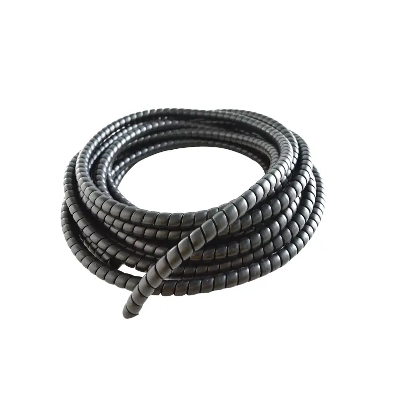
Bend radius matters because a hydraulic hose must contain pressure while its tube, reinforcement, and cover deform around a curve. A Parker SAE 100R2 hose, for example, lists a 180 mm minimum bend radius at 1/2-inch ID, while the 1-inch version requires 300 mm. The same series carries working pressures from 4,000 psi at 1/2 inch to 2,400 psi at 1 inch. Routing below the published radius increases reinforcement strain, encourages flattening, and concentrates bending close to the coupling. ISO 18752:2025 also separates hydraulic hoses by pressure class and performance grade rather than treating all constructions as equally flexible.
A hydraulic hose is a pressure vessel that can bend, not an ordinary rubber tube. A typical two-wire braided design contains an oil-resistant inner tube, two steel-wire reinforcement layers, and an abrasion-resistant outer cover. When the hose bends, the outside of the curve stretches while the inside compresses. At the manufacturer's stated radius, those layers can move within the geometry for which the hose was designed. At a tighter radius, the difference between outer-side tension and inner-side compression becomes larger, especially during repeated pressure cycling.
Size changes the allowable geometry substantially. Parker's SAE 100R2-type 302 series lists 100 mm minimum radius for a 1/4-inch hose, 130 mm for 3/8 inch, 180 mm for 1/2 inch, 240 mm for 3/4 inch, and 300 mm for 1 inch. Moving from 1/2 inch to 1 inch therefore increases the required radius by about 67%, even though the nominal inside diameter only doubles. The same catalog shows a further jump to 420 mm at 1-1/4 inch and 630 mm at 2 inches.
| Nominal hose ID | Example minimum bend radius | Example working pressure |
|---|---|---|
| 1/4 in | 100 mm | 5,800 psi |
| 3/8 in | 130 mm | 4,750 psi |
| 1/2 in | 180 mm | 4,000 psi |
| 3/4 in | 240 mm | 3,100 psi |
| 1 in | 300 mm | 2,400 psi |
| 2 in | 630 mm | 1,150 psi |
Those figures explain why copying a routing path from a smaller hose can produce a poor custom assembly. A machine may have 200 mm of free space around a valve block, enough for a 1/2-inch example requiring 180 mm but not enough for a 3/4-inch version requiring 240 mm. Forcing the larger assembly into the same space can flatten its cross-section before any external damage becomes visible.
Flattening matters because flow area depends on the internal shape remaining close to round. A hose does not have to collapse completely before fluid behavior changes. Local deformation narrows the passage, raises local fluid velocity, and adds pressure loss. In systems operating near the upper end of their flow range, a bend that reduces effective cross-sectional area by even 10% requires fluid velocity through that restricted section to rise by roughly 11% for the same volumetric flow.
Pressure cycling adds another layer of mechanical strain. Gates states that one SAE 100R2 G2 two-wire braid hose configuration was tested to 600,000 impulse cycles, described by the manufacturer as three times its referenced industry level. That type of qualification is performed on a hose assembled and routed under defined conditions; it should not be read as permission to install the hose below its published radius. A 600,000-cycle qualification and a poorly routed field installation are mechanically different situations.
A hose can physically bend tighter than its catalog radius and still be unsuitable for continuous service in that position.
The distinction is easy to miss during assembly. An installer can often push a hose into a sharp curve by hand, connect both fittings, and see no immediate leak. Internal reinforcement still has to survive pressure pulses after the machine enters service. In a circuit cycling once every 10 seconds, 600,000 machine movements would accumulate in about 1,667 operating hours. Routing geometry therefore affects millions of individual changes in wire position over the working life of frequently used equipment.
The fitting area deserves extra space because the coupling itself cannot flex like the hose body. If a bend begins immediately behind the crimp, movement becomes concentrated in a short section where flexible and rigid components meet. Repeated flexing there can produce cover cracking, reinforcement fatigue, or leakage. A better layout leaves enough straight hose after the coupling for bending to begin gradually, while an elbow fitting can redirect the connection when the available envelope is small.
Fitting orientation can sometimes solve a bend-radius problem without increasing total hose length. A correctly clocked 45-degree or 90-degree fitting can send the hose toward its routing path instead of requiring the hose body to make the same turn. On assemblies fitted with elbows at both ends, orientation also controls torsion. A hose installed with a visible spiral in its layline has been twisted, and pressure cycling then acts on a structure experiencing both torsion and bending.
Length should be selected with the same geometry in mind. A hose that is 5% too short can become taut as a cylinder reaches full extension, pulling the bend toward the fitting and decreasing its radius. Adding excessive length is not automatically safer; extra hose can create a hanging loop that contacts steel brackets, adjacent hose assemblies, tires, guards, or hot surfaces. The required length is the amount that maintains an acceptable curve through every machine position without excessive slack.
Mobile equipment makes the check more demanding because one measurement rarely represents the complete installation. A loader arm, excavator boom, forklift mast, agricultural attachment, or steering cylinder may move through 90 degrees or more while the hose changes position continuously. Radius should be checked with cylinders retracted, partly extended, and fully extended rather than with the equipment parked in one convenient position.
A practical routing review can therefore record several measurements before an assembly is made:
-
Port-to-port distance at minimum and maximum machine extension
-
Smallest available radius around nearby structures
-
Hose ID and OD rather than nominal size alone
-
Minimum bend radius from the exact hose datasheet
-
Required fitting angle and elbow orientation
-
Maximum working pressure and expected pressure peaks
-
Fluid and ambient temperature
-
Areas where the hose may contact metal during movement
Temperature belongs in the same review because material behavior changes across the permitted range. ISO 18752:2025 specifies ten pressure classes, four grades, and seven hose types covering nominal sizes from 5 to 102. For listed oil-based hydraulic fluids, several types are rated for service from -40°C to +100°C, while other types extend to +120°C; water-based fluid applications have different temperature limits. A hose selected for pressure alone may therefore be wrong for the temperature and routing conditions even when its dimensions fit.
Hose construction also changes packaging requirements. Two-wire braid products often combine moderate flexibility with high working pressure, while multi-spiral reinforcement used in severe-pressure applications generally produces a stiffer assembly. Compact constructions can provide smaller outside diameters or reduced catalog bend radii, which can be useful when an OEM has only 150–200 mm of routing space around pumps or manifolds. Published data for the exact product series should still take precedence over assumptions based on appearance.
The same approach applies when a hydraulic circuit sits beside a heavy duty industrial hose. Two hoses with similar outside diameters may carry completely different reinforcement structures, pressure ratings, media, and bend limits. Using the radius from an air, water, chemical, material-handling, or industrial transfer hose as a substitute for hydraulic-hose data can produce the wrong routing geometry even when both products fit through the same clamp.
Pressure rating adds another useful comparison. In Parker's example 302 series, the 1/4-inch hose is rated at 5,800 psi with a 100 mm minimum bend radius, while the 2-inch version is rated at 1,150 psi and requires 630 mm. The larger hose needs a bend radius 530% greater than the 1/4-inch size even though its catalog working pressure is much lower. Diameter, reinforcement layout, and construction therefore matter alongside pressure when estimating required space.
Machine designers can reduce routing problems before prototype assembly by allocating hose envelopes in CAD rather than drawing only a centerline between two ports. If a selected hose requires a 240 mm radius, the model should reserve the physical arc plus clearance for movement, clamps, neighboring hoses, and manufacturing tolerances. A route that exactly matches 240 mm on a static CAD model leaves little allowance for assembly variation or component movement.
Manufacturing tolerances should also be considered when specifying custom assemblies. Overall hose length, coupling insertion, elbow orientation, and port position each have production tolerances. When the installation allows almost no spare geometry, a relatively small dimensional difference can move the bend closer to the coupling or nearby structure. Providing reasonable clearance is more dependable than designing an assembly to sit exactly on its catalog minimum radius.
Inspection data can help confirm whether the original routing was appropriate. Cover cracking concentrated on the outside of one curve, flattening on the inside of a bend, repeated leakage near one fitting, exposed wire reinforcement, or recurring replacement at the same location all justify measuring the installed radius. If three replacement hoses fail at approximately the same point, replacing the fourth with an identical assembly without reviewing routing leaves the same mechanical condition in place.
SAE-style hose families also show why part-number-level data matters. Parker lists 301 and 302 hoses under SAE 100R2-related classifications, yet working-pressure and temperature details can differ between product constructions and sizes. ISO 18752 was updated again in 2025, reinforcing the practice of checking the current manufacturer's technical sheet rather than relying on an old workshop chart, a previous machine model, or the dimensions of the removed hose.
For a custom assembly, pressure, ID, fittings, length, and bend radius should be specified together. A 4,000 psi 1/2-inch assembly that meets pressure requirements but is forced into a 120 mm curve when its published minimum is 180 mm is still outside its stated routing limit. Increasing available radius to 180 mm represents a 50% increase in radius, often achievable through a different elbow orientation, a slightly revised hose length, a relocated clamp, or a hose series designed for tighter packaging.